LOD in BIM Explained: What LOD 200, 300, 350, 400 and 500 Mean
A plain-English guide to LOD in BIM (Level of Development): what each level contains, which stage of a project it suits, and how to specify LOD in a BIM scope.
When you ask for BIM services, one of the first questions is about LOD in BIM: what LOD do you need? Getting this right controls cost, effort and what the model can be used for. Model too little and the model can't support coordination; model too much and you pay for detail nobody uses.
Level of Development, not level of detail
LOD stands for Level of Development. It describes how far an element in the model has been developed, meaning both how detailed its geometry is and how reliable its information is. The widely used definitions come from the BIMForum LOD Specification.
The key idea: LOD applies to each element, not to the whole model. A model at "LOD 350" overall may have some elements at LOD 300 and others at LOD 400.
The levels
LOD 100: concept
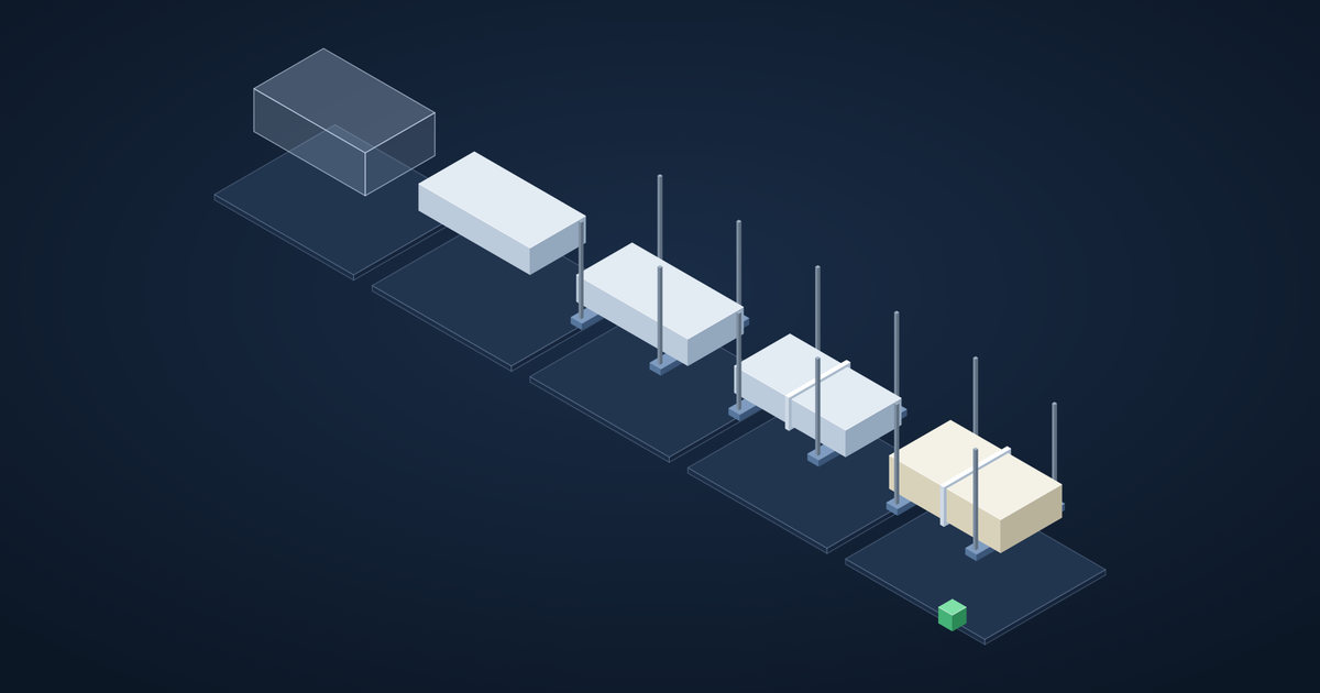
The element is shown as a symbol or a general mass. Useful for early studies of area and volume. Rarely used for engineering deliverables.
LOD 200: approximate geometry
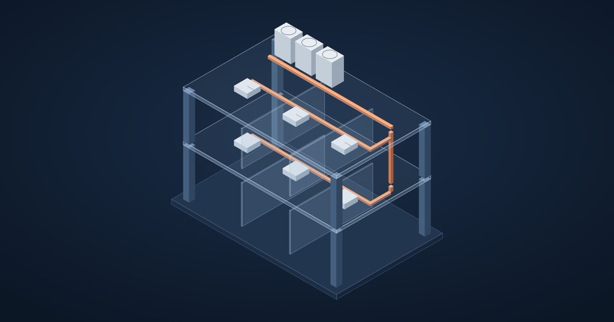
Elements are modelled as generic placeholders with approximate size, shape, location and orientation. For example, an air handling unit as a box of roughly the right size. Use: schematic design, early space planning, rough quantities.
LOD 300: precise geometry
Elements are modelled with accurate size, shape, location and orientation, as they would appear on construction documents. Use: design development and construction drawings, reliable quantities.
LOD 350: coordination
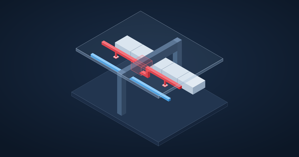
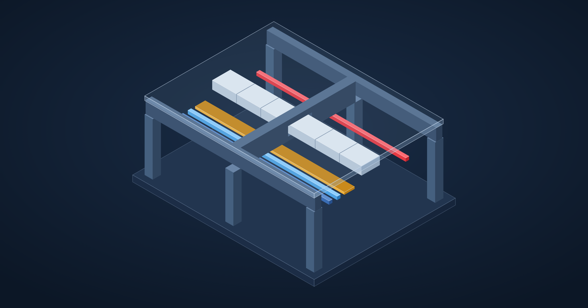
LOD 300 plus the interfaces with other systems: supports, hangers, connections, clearances and access zones. This is the level needed for meaningful clash detection, because many real clashes are with supports and clearance zones, not the pipe itself. Use: MEP coordination and coordinated services drawings.
LOD 400: fabrication
Elements are modelled with enough detail and accuracy to be fabricated and installed: exact fittings, connections and assembly information. Use: shop drawings, prefabrication, steel fabrication (for example from Tekla models), ductwork fabrication.
LOD 500: as-built
Elements are verified against what was actually installed on site. The term is used for field-verified models handed over for operation and maintenance. Use: facility management, future renovations.
Which LOD at which stage?
| Project stage | Typical LOD |
|---|---|
| Concept / schematic design | 200 |
| Design development | 300 |
| Construction drawings | 300 |
| MEP coordination | 350 |
| Shop drawings and fabrication | 400 |
| Handover / facility management | 500 |
How to specify LOD in your BIM scope
A clear scope avoids arguments later. Include:
- A model element table listing element categories (walls, beams, ducts, pipes, cable trays, equipment) with the required LOD at each stage.
- Information requirements: which parameters each element must carry, such as system name, size, material or equipment tag.
- Minimum sizes to model: for instance, pipes and conduits below a certain diameter may be excluded from coordination.
- Deliverables: native files (RVT), IFC exports, drawings and clash reports, and the software version.
Common mistakes when specifying LOD
- Asking for LOD 400 everywhere. Fabrication detail for every element costs a lot and slows the model down. Ask for it only where something will actually be fabricated from the model, such as steelwork or ductwork.
- Not saying what information is needed. Geometry alone is not enough; if you want schedules or facility management data, list the parameters.
- Ignoring supports and clearances. A model at LOD 300 can look clash-free while hangers, insulation and access zones still collide on site. Coordination needs LOD 350.
- Calling a design model "as-built". LOD 500 means checked against site. Without a site survey, it's still a design model.
Our approach
We model architecture, structure, MEP and fire protection in Revit at the LOD each stage needs, typically LOD 300 for design drawings and LOD 350 for coordination, with LOD 400 for steel fabrication in Tekla and LOD 500 as-built models at handover. See our BIM modelling and coordination services or ask us for a quotation.