Combined Services Drawings (CSD): What They Are and Why Contractors Need Them
What a combined services drawing (CSD) shows, how it is produced from a coordinated BIM model, who signs it off, and the mistakes that cause rework on site.

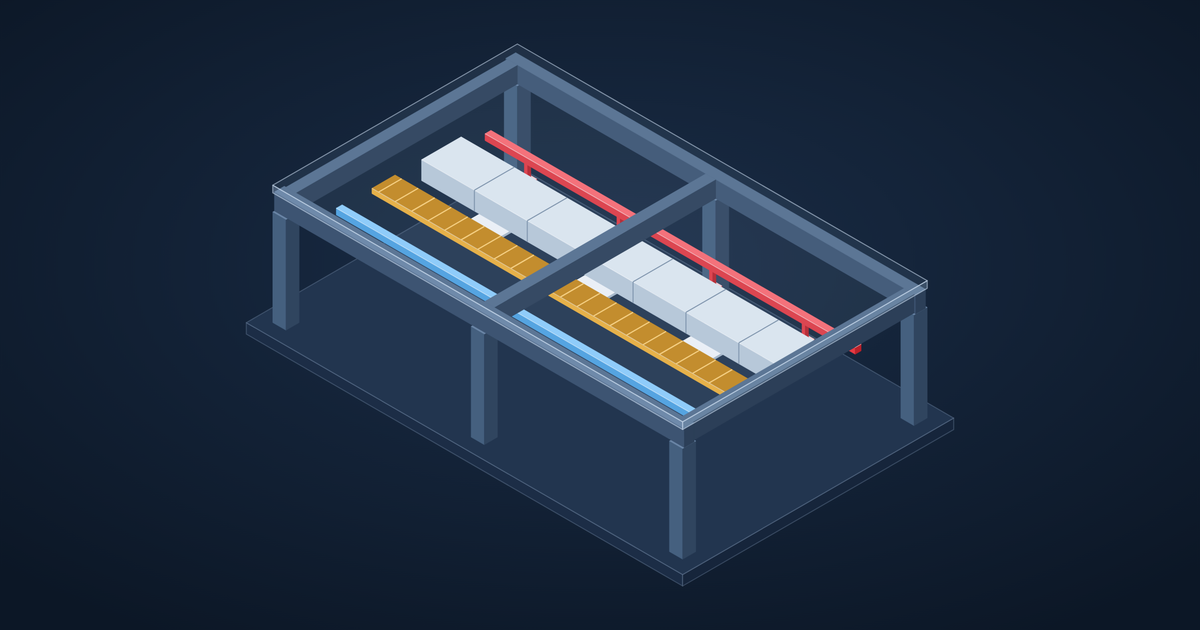
A combined services drawing (CSD), also called a coordinated services drawing, shows every building service in an area on one drawing: ducts, pipes, cable trays, sprinkler mains and drainage, with their sizes, levels and clearances. It is the drawing that proves all the services actually fit in the ceiling void and shafts before anything is installed.
Why CSDs matter
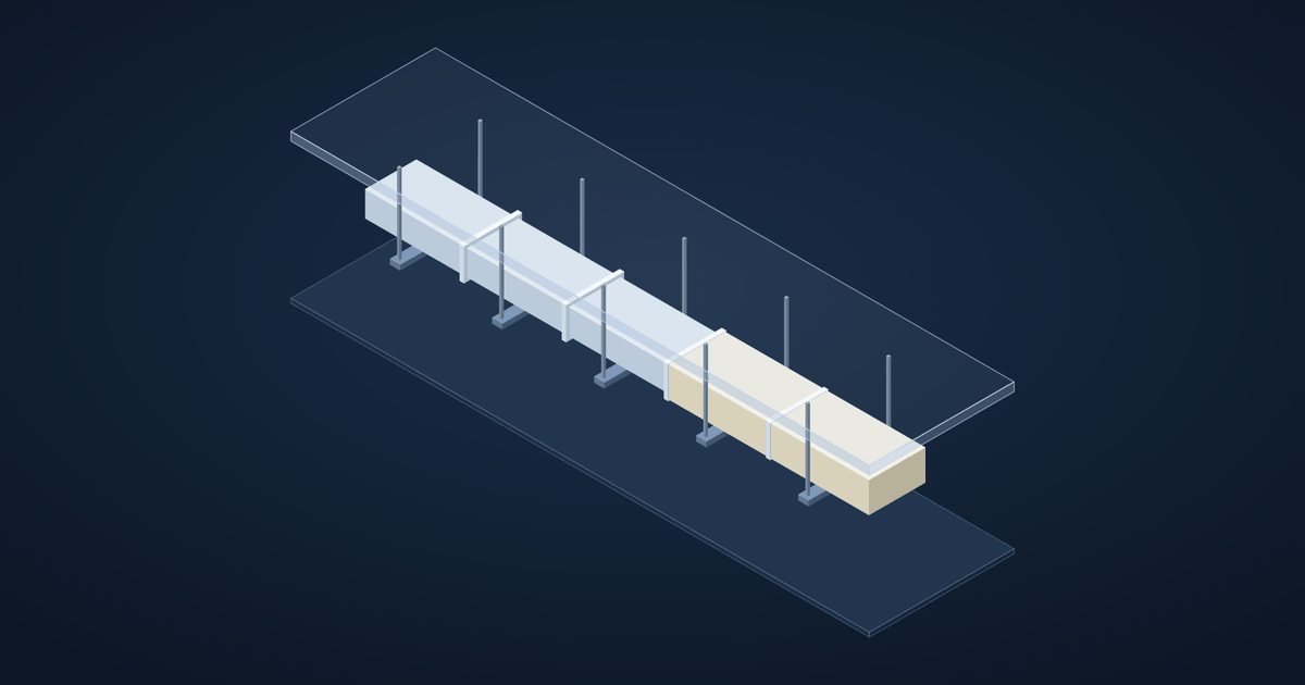
Each MEP discipline is usually designed separately: the HVAC engineer lays out ducts, the electrical engineer cable trays, the fire engineer sprinkler mains. Each drawing works on its own. Put them together in a 600 mm ceiling void under a 700 mm beam and they often don't.
Without a CSD, these clashes are found on site, where they cost the most: installed work is taken down, ducts are re-made, beams get cored without structural approval, and the ceiling height drops. A CSD moves that problem to the drawing board.
What a CSD shows
A good combined services drawing includes:
- Every service in the area, drawn in a distinct line type or colour
- Sizes of ducts, pipes and trays
- Levels: bottom-of-duct, centre-line or bottom-of-tray levels from finished floor
- Sections through the most congested zones, showing the stacking order
- Structure: beams, columns and slab edges with their depths
- Clearances for insulation, access, maintenance and the ceiling system
- Sleeves and openings through walls and beams, cross-referenced to builder's work drawings
The stacking order
Most CSDs follow an agreed priority so decisions are consistent:
- Gravity drainage first, because it needs a continuous fall and can't go up and over obstacles
- Large ducts, which have the least flexibility
- Sprinkler mains and other large pipes
- Cable trays, with space above for pulling cables
- Small pipes and conduits, which can bend around everything else
Lighting and ceiling grid zones are reserved at the bottom of the void.
How CSDs are produced from BIM
Today most CSDs come from a coordinated BIM model rather than overlaid 2D drawings:
- Each discipline is modelled in Revit at LOD 350, including supports and insulation
- The models are combined and checked with clash detection
- Clashes are resolved by rerouting, resizing or changing levels, with design changes agreed by each engineer
- Plans and sections are cut from the coordinated model and annotated as the CSD
Because the drawing comes from the model, plan and section always agree.
Who signs it off?
Usually the MEP contractor produces the CSD from the consultant's design, and the consultant reviews it for design intent. The main contractor checks it against the structure and architectural ceilings, and on many projects it must be approved before installation starts. Make the approval route clear in the contract.
Common mistakes
- Leaving out insulation and supports. A duct that fits without insulation and hangers often doesn't fit with them.
- No sections. Plans alone can't show stacking in congested corridors.
- Ignoring access. Valves, dampers and fan coil units need space to be maintained.
- Coordinating too late. CSDs started after installation begins only document problems.
How we help
We model MEP and fire protection services in Revit, coordinate them with the structure, and produce combined services and builder's work drawings for contractors and consultants in India and overseas. See our BIM coordination services and BIM outsourcing for contractors, or send us your drawings.